
Chapter 3
Data link layer
Data link layer :
Data link layer works between two hosts which are directly connected in some sense. This direct connection could be point to point or broadcast. Systems on broadcast network are said to be on same link. The work of data link layer tends to get more complex when it is dealing with multiple hosts on single collision domain.
Data link layer is responsible for converting data stream to signals bit by bit and to send that over the underlying hardware. At the receiving end, Data link layer picks up data from hardware which are in the form of electrical signals, assembles them in a recognizable frame format, and hands over to upper layer.
Data link layer has two sub-layers:
Logical Link Control: It deals with protocols, flow-control, and error control
Media Access Control: It deals with actual control of media
Functionality of Data-link Layer
Data link layer does many tasks on behalf of upper layer. These are:
Framing
Data-link layer takes packets from Network Layer and encapsulates them into Frames.Then, it sends each frame bit-by-bit on the hardware. At receiver’ end, data link layer picks up signals from hardware and assembles them into frames.
Addressing
Data-link layer provides layer-2 hardware addressing mechanism. Hardware address is assumed to be unique on the link. It is encoded into hardware at the time of manufacturing.
Synchronization
When data frames are sent on the link, both machines must be synchronized in order to transfer to take place.
Error Control
Sometimes signals may have encountered problem in transition and the bits are flipped.These errors are detected and attempted to recover actual data bits. It also provides error reporting mechanism to the sender.
Flow Control
Stations on same link may have different speed or capacity. Data-link layer ensures flow control that enables both machine to exchange data on same speed.
Multi-Access
When host on the shared link tries to transfer the data, it has a high probability of collision. Data-link layer provides mechanism such as CSMA/CD to equip capability of accessing a shared media among multiple Systems.
Types of Errors
There may be three types of errors:
- Single bit error
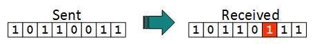 In a frame, there is only one bit, anywhere though, which is corrupt.
 - Multiple bits error
 Frame is received with more than one bits in corrupted state.
 - Burst error
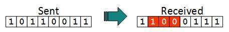 Frame contains more than1 consecutive bits corrupted.
Error control mechanism may involve two possible ways:
- Error detection
- Error correction
Error Detection
Errors in the received frames are detected by means of Parity Check and Cyclic Redundancy Check (CRC). In both cases, few extra bits are sent along with actual data to confirm that bits received at other end are same as they were sent. If the counter-check at receiver’ end fails, the bits are considered corrupted.
Parity Check
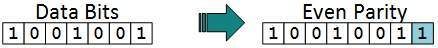
One extra bit is sent along with the original bits to make number of 1s either even in case of even parity, or odd in case of odd parity.
The sender while creating a frame counts the number of 1s in it. For example, if even parity is used and number of 1s is even then one bit with value 0 is added. This way number of 1s remains even.If the number of 1s is odd, to make it even a bit with value 1 is added.
The receiver simply counts the number of 1s in a frame. If the count of 1s is even and even parity is used, the frame is considered to be not-corrupted and is accepted. If the count of 1s is odd and odd parity is used, the frame is still not corrupted.
If a single bit flips in transit, the receiver can detect it by counting the number of 1s. But when more than one bits are erro neous, then it is very hard for the receiver to detect the error.
Cyclic Redundancy Check (CRC)
CRC is a different approach to detect if the received frame contains valid data. This technique involves binary division of the data bits being sent. The divisor is generated using polynomials. The sender performs a division operation on the bits being sent and calculates the remainder. Before sending the actual bits, the sender adds the remainder at the end of the actual bits. Actual data bits plus the remainder is called a codeword. The sender transmits data bits as codewords.
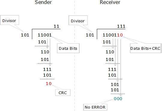
At the other end, the receiver performs division operation on codewords using the same CRC divisor. If the remainder contains all zeros the data bits are accepted, otherwise it is considered as there some data corruption occurred in transit.
Error Correction
In the digital world, error correction can be done in two ways:
- Backward Error Correction When the receiver detects an error in the data received, it requests back the sender to retransmit the data unit.
- Forward Error Correction When the receiver detects some error in the data received, it executes error-correcting code, which helps it to auto-recover and to correct some kinds of errors.
The first one, Backward Error Correction, is simple and can only be efficiently used where retransmitting is not expensive. For example, fiber optics. But in case of wireless transmission retransmitting may cost too much. In the latter case, Forward Error Correction is used.
To correct the error in data frame, the receiver must know exactly which bit in the frame is corrupted. To locate the bit in error, redundant bits are used as parity bits for error detection.For example, we take ASCII words (7 bits data), then there could be 8 kind of information we need: first seven bits to tell us which bit is error and one more bit to tell that there is no error.
For m data bits, r redundant bits are used. r bits can provide 2r combinations of information. In m+r bit codeword, there is possibility that the r bits themselves may get corrupted. So the number of r bits used must inform about m+r bit locations plus no-error information, i.e. m+r+1.
Two types of mechanisms can be deployed to control the flow:
- Stop and WaitThis flow control mechanism forces the sender after transmitting a data frame to stop and wait until the acknowledgement of the data-frame sent is received.
- Sliding WindowIn this flow control mechanism, both sender and receiver agree on the number of data-frames after which the acknowledgement should be sent. As we learnt, stop and wait flow control mechanism wastes resources, this protocol tries to make use of underlying resources as much as possible.
Error Control
When data-frame is transmitted, there is a probability that data-frame may be lost in the transit or it is received corrupted. In both cases, the receiver does not receive the correct data-frame and sender does not know anything about any loss.In such case, both sender and receiver are equipped with some protocols which helps them to detect transit errors such as loss of data-frame. Hence, either the sender retransmits the data-frame or the receiver may request to resend the previous data-frame.
Requirements for error control mechanism:
- Error detection - The sender and receiver, either both or any, must ascertain that there is some error in the transit.
- Positive ACK - When the receiver receives a correct frame, it should acknowledge it.
- Negative ACK - When the receiver receives a damaged frame or a duplicate frame, it sends a NACK back to the sender and the sender must retransmit the correct frame.
- Retransmission: The sender maintains a clock and sets a timeout period. If an acknowledgement of a data-frame previously transmitted does not arrive before the timeout the sender retransmits the frame, thinking that the frame or it’s acknowledgement is lost in transit.
There are three types of techniques available which Data-link layer may deploy to control the errors by Automatic Repeat Requests (ARQ):
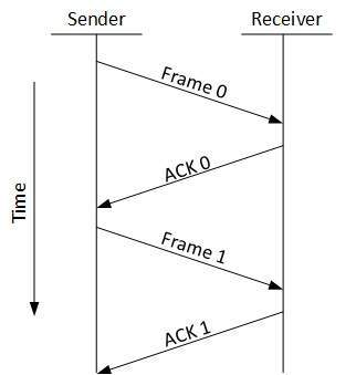
Stop-and-wait ARQ
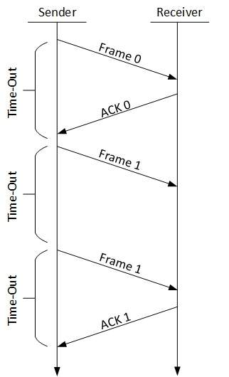 The following transition may occur in Stop-and-Wait ARQ:
- The sender maintains a timeout counter.
- When a frame is sent, the sender starts the timeout counter.
- If acknowledgement of frame comes in time, the sender transmits the next frame in queue.
- If acknowledgement does not come in time, the sender assumes that either the frame or its acknowledgement is lost in transit. Sender retransmits the frame and starts the timeout counter.
- If a negative acknowledgement is received, the sender retransmits the frame.
Go-Back-N ARQ
Stop and wait ARQ mechanism does not utilize the resources at their best.When the acknowledgement is received, the sender sits idle and does nothing. In Go-Back-N ARQ method, both sender and receiver maintain a window.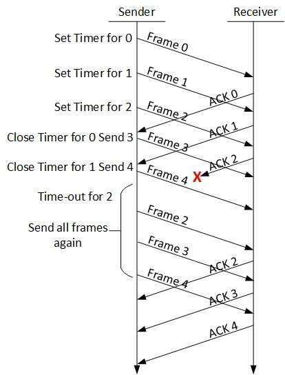 The sending-window size enables the sender to send multiple frames without receiving the acknowledgement of the previous ones. The receiving-window enables the receiver to receive multiple frames and acknowledge them. The receiver keeps track of incoming frame’s sequence number.When the sender sends all the frames in window, it checks up to what sequence number it has received positive acknowledgement. If all frames are positively acknowledged, the sender sends next set of frames. If sender finds that it has received NACK or has not receive any ACK for a particular frame, it retransmits all the frames after which it does not receive any positive ACK.
Selective Repeat ARQ
In Go-back-N ARQ, it is assumed that the receiver does not have any buffer space for its window size and has to process each frame as it comes. This enforces the sender to retransmit all the frames which are not acknowledged.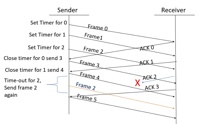 In Selective-Repeat ARQ, the receiver while keeping track of sequence numbers, buffers the frames in memory and sends NACK for only frame which is missing or damaged.The sender in this case, sends only packet for which NACK is received.
Network Control Protocol (NCP):
Network Control Protocol (NCP) was an early protocol implemented by ARPANET, the world's first operational packet-switching network that later evolved into what became the Internet. NCP allowed users to access and use computers and devices at remote locations and to transmit files between computers. NCP provided the middle layer of the protocol stack, and enabled application services such as email and file transfer.
Whether the term is Network Control Protocol or Network Control Program is a matter of some debate, as both terms are used to refer to this ARPANET protocol.HDLC Protocol - High-level Data Link Control
- HDLC - Short for High-level Data Link Control, a transmission protocol used at the data link layer (layer 2) of the OSI seven layer model for data communications. The HDLC protocol embeds information in a data frame that allows devices to control data flow and correct errors. HDLC is an ISO standard developed from the Synchronous Data Link Control (SDLC) standard proposed by IBM in the 1970's. HDLC NRM (also known as SDLC) .HDLC is a bit oriented protocol that supports both half-duplex and full-duplex communication over point to point & multipoint link.For any HDLC communications session, one station is designated primary and the other secondary. A session can use one of the following connection modes, which determine how the primary and secondary stations interact.• Normal unbalanced: The secondary station responds only to the primary station.
• Asynchronous: The secondary station can initiate a message.
• Asynchronous balanced: Both stations send and receive over its part of a duplex line.
Point-to-Point Protocol
The Point-to-Point Protocol (PPP) is an encapsulation protocol for transporting IP traffic across point-to-point links. PPP is made up of three primary components:
- Link Control Protocol (LCP)—Establishes working connections between two points.
- Authentication protocol—Enables secure connections between two points.
- Network control protocol (NCP)—Initializes the PPP protocol stack to handle multiple Network Layer protocols, such as IPv4, IPv6, and Connectionless Network Protocol (CLNP).
This topic contains the following sections:
Link Control Protocol
LCP is responsible for establishing, maintaining, and tearing down a connection between two endpoints. LCP also tests the link and determines whether it is active. LCP establishes a point-to-point connection as follows:
- LCP must first detect a clocking signal on each endpoint. However, because the clocking signal can be generated by a network clock and shared with devices on the network, the presence of a clocking signal is only a preliminary indication that the link might be functioning.
- When a clocking signal is detected, a PPP host begins transmitting PPP Configure-Request packets.
- If the remote endpoint on the point-to-point link receives the Configure-Request packet, it transmits a Configure-Acknowledgement packet to the source of the request.
- After receiving the acknowledgement, the initiating endpoint identifies the link as established. At the same time, the remote endpoint sends its own request packets and processes the acknowledgement packets. In a functioning network, both endpoints treat the connection as established.
Network Control Protocols
After authentication is completed, the PPP connection is fully established. At this point, any higher level protocols (for example, IP protocols) can initialize and perform their own negotiations and authentication.
PPP NCPs include support for the following protocols. IPCP and IPv6CP are the most widely used on SRX Series devices.
- IPCP—IP Control Protocol
- IPv6CP—IPv6 Control Protocol
- OSINLCP—OSI Network Layer Control Protocol (includes IS-IS, ES-IS, CLNP, and IDRP)
Token Bus:
Token bus is a network implementing the token ring protocol over a "virtual ring" on a coaxial cable. A token is passed around the network nodes and only the node possessing the token may transmit. If a node doesn't have anything to send, the token is passed on to the next node on the virtual ring. Each node must know the address of its neighbor in the ring, so a special protocol is needed to notify the other nodes of connections to, and disconnections from, the ring.
Token bus was standardized by IEEE standard 802.4. It is mainly used for industrial applications. Token bus was used by General Motors for their Manufacturing Automation Protocol (MAP) standardization effort. This is an application of the concepts used in token ring networks. The main difference is that the endpoints of the bus do not meet to form a physical ring.
Due to difficulties handling device failures and adding new stations to a network, token ring gained a reputation for being unreliable and difficult to upgrade. Bus networks, such as Ethernet, had a more flexible and reliable physical architecture, but Ethernet's access protocol could not absolutely guarantee a maximum time any station would have to wait to access the network, so was thought to be unsuitable for manufacturing automation applications. The Token bus protocol was created to combine the benefits of a physical bus network with the deterministic access protocol of a token ring network.


No comments:
Post a Comment