

Chapter 2
Physical layer
Introduction -
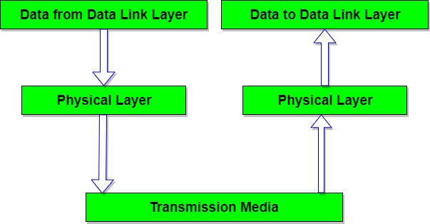
Physical layer is the lowest layer of the OSI reference model. It is responsible for sending bits from one computer to another. This layer is not concerned with the meaning of the bits and deals with the physical connection to the network and with transmission and reception of signals.
Overview of data -
Signals
When data is sent over physical medium, it needs to be first converted into electromagnetic signals. Data itself can be analog such as human voice, or digital such as file on the disk.Both analog and digital data can be represented in digital or analog signals.
- Digital SignalsDigital signals are discrete in nature and represent sequence of voltage pulses. Digital signals are used within the circuitry of a computer system.
- Analog SignalsAnalog signals are in continuous wave form in nature and represented by continuous electromagnetic waves.
Transmission Media
The media over which the information between two computer systems is sent, called transmission media. Transmission media comes in two forms.
- Guided MediaAll communication wires/cables are guided media, such as UTP, coaxial cables, and fiber Optics. In this media, the sender and receiver are directly connected and the information is send (guided) through it.
- Twisted Pair Cable
- A twisted pair cable is made of two plastic insulated copper wires twisted together to form a single media. Out of these two wires, only one carries actual signal and another is used for ground reference. The twists between wires are helpful in reducing noise (electro-magnetic interference) and crosstalk.

There are two types of twisted pair cables:- Shielded Twisted Pair (STP) Cable
- Unshielded Twisted Pair (UTP) Cable
STP cables comes with twisted wire pair covered in metal foil. This makes it more indifferent to noise and crosstalk.UTP has seven categories, each suitable for specific use. In computer networks, Cat-5, Cat-5e, and Cat-6 cables are mostly used. UTP cables are connected by RJ45 connectors.Coaxial Cable
Coaxial cable has two wires of copper. The core wire lies in the center and it is made of solid conductor.The core is enclosed in an insulating sheath.The second wire is wrapped around over the sheath and that too in turn encased by insulator sheath.This all is covered by plastic cover.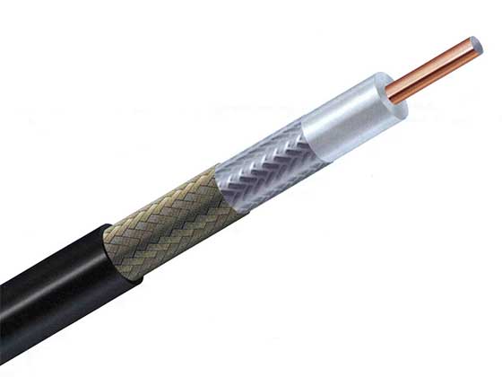
Because of its structure,the coax cable is capable of carrying high frequency signals than that of twisted pair cable.The wrapped structure provides it a good shield against noise and cross talk. Coaxial cables provide high bandwidth rates of up to 450 mbps.There are three categories of coax cables namely, RG-59 (Cable TV), RG-58 (Thin Ethernet), and RG-11 (Thick Ethernet). RG stands for Radio Government.Cables are connected using BNC connector and BNC-T. BNC terminator is used to terminate the wire at the far ends. Fiber Optics
Fiber Optic works on the properties of light. When light ray hits at critical angle it tends to refracts at 90 degree. This property has been used in fiber optic. The core of fiber optic cable is made of high quality glass or plastic. From one end of it light is emitted, it travels through it and at the other end light detector detects light stream and converts it to electric data.Fiber Optic provides the highest mode of speed. It comes in two modes, one is single mode fiber and second is multimode fiber. Single mode fiber can carry a single ray of light whereas multimode is capable of carrying multiple beams of light.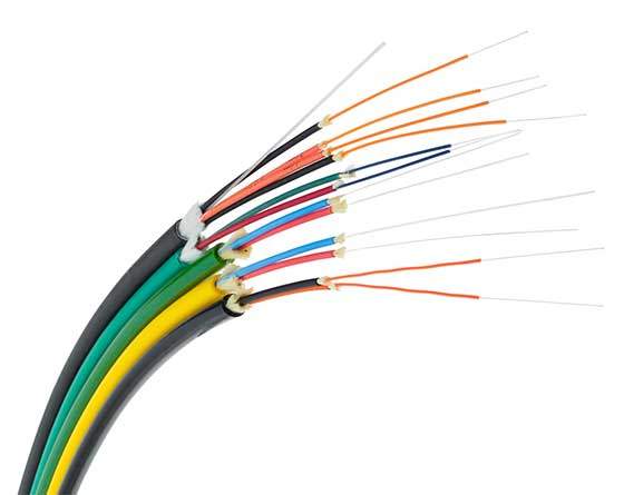 Fiber Optic also comes in unidirectional and bidirectional capabilities. To connect and access fiber optic special type of connectors are used. These can be Subscriber Channel (SC), Straight Tip (ST), or MT-RJ.
- Unguided MediaWireless or open air space is said to be unguided media, because there is no connectivity between the sender and receiver. Information is spread over the air, and anyone including the actual recipient may collect the information.
Radio Transmission
Radio frequency is easier to generate and because of its large wavelength it can penetrate through walls and structures alike.Radio waves can have wavelength from 1 mm – 100,000 km and have frequency ranging from 3 Hz (Extremely Low Frequency) to 300 GHz (Extremely High Frequency). Radio frequencies are sub-divided into six bands.Radio waves at lower frequencies can travel through walls whereas higher RF can travel in straight line and bounce back.The power of low frequency waves decreases sharply as they cover long distance. High frequency radio waves have more power.Lower frequencies such as VLF, LF, MF bands can travel on the ground up to 1000 kilometers, over the earth’s surface.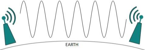
Radio waves of high frequencies are prone to be absorbed by rain and other obstacles. They use Ionosphere of earth atmosphere. High frequency radio waves such as HF and VHF bands are spread upwards. When they reach Ionosphere, they are refracted back to the earth.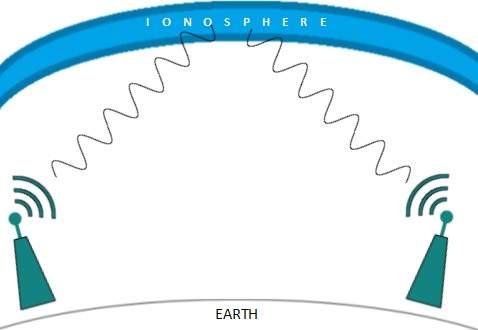
Microwave Transmission
Electromagnetic waves above 100 MHz tend to travel in a straight line and signals over them can be sent by beaming those waves towards one particular station. Because Microwaves travels in straight lines, both sender and receiver must be aligned to be strictly in line-of-sight.Microwaves can have wavelength ranging from 1 mm – 1 meter and frequency ranging from 300 MHz to 300 GHz.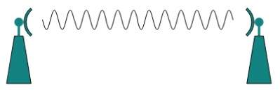
Microwave antennas concentrate the waves making a beam of it. As shown in picture above, multiple antennas can be aligned to reach farther. Microwaves have higher frequencies and do not penetrate wall like obstacles.Microwave transmission depends highly upon the weather conditions and the frequency it is using.
Infrared Transmission
Infrared wave lies in between visible light spectrum and microwaves. It has wavelength of 700-nm to 1-mm and frequency ranges from 300-GHz to 430-THz.Infrared wave is used for very short range communication purposes such as television and it’s remote. Infrared travels in a straight line hence it is directional by nature. Because of high frequency range, Infrared cannot cross wall-like obstacles.Light Transmission
Highest most electromagnetic spectrum which can be used for data transmission is light or optical signaling. This is achieved by means of LASER.Because of frequency light uses, it tends to travel strictly in straight line.Hence the sender and receiver must be in the line-of-sight. Because laser transmission is unidirectional, at both ends of communication the laser and the photo-detector needs to be installed. Laser beam is generally 1mm wide hence it is a work of precision to align two far receptors each pointing to lasers source.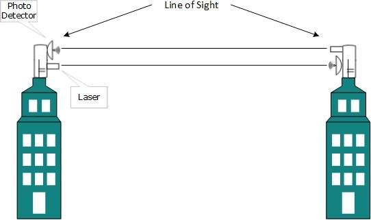
Laser works as Tx (transmitter) and photo-detectors works as Rx (receiver).Lasers cannot penetrate obstacles such as walls, rain, and thick fog. Additionally, laser beam is distorted by wind, atmosphere temperature, or variation in temperature in the path.Laser is safe for data transmission as it is very difficult to tap 1mm wide laser without interrupting the communication channel.
Multiplexing
Multiplexing is a technique to mix and send multiple data streams over a single medium. This technique requires system hardware called multiplexer (MUX) for multiplexing the streams and sending them on a medium, and de-multiplexer (DMUX) which takes information from the medium and distributes to different destinations.
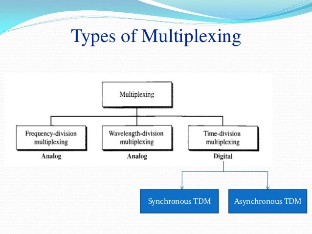
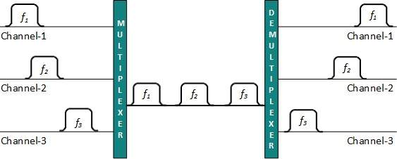
Frequency Division Multiplexing
When the carrier is frequency, FDM is used. FDM is an analog technology. FDM divides the spectrum or carrier bandwidth in logical channels and allocates one user to each channel. Each user can use the channel frequency independently and has exclusive access of it. All channels are divided in such a way that they do not overlap with each other. Channels are separated by guard bands. Guard band is a frequency which is not used by either channel.
Time Division Multiplexing
TDM is applied primarily on digital signals but can be applied on analog signals as well. In TDM the shared channel is divided among its user by means of time slot. Each user can transmit data within the provided time slot only. Digital signals are divided in frames, equivalent to time slot i.e. frame of an optimal size which can be transmitted in given time slot.
TDM works in synchronized mode. Both ends, i.e. Multiplexer and De-multiplexer are timely synchronized and both switch to next channel simultaneously.
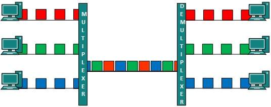 When channel A transmits its frame at one end,the De-multiplexer provides media to channel A on the other end.As soon as the channel A’s time slot expires, this side switches to channel B. On the other end, the De-multiplexer works in a synchronized manner and provides media to channel B. Signals from different channels travel the path in interleaved manner.
Wavelength Division Multiplexing
Light has different wavelength (colors). In fiber optic mode, multiple optical carrier signals are multiplexed into an optical fiber by using different wavelengths. This is an analog multiplexing technique and is done conceptually in the same manner as FDM but uses light as signals.
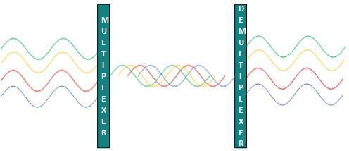 Further, on each wavelength time division multiplexing can be incorporated to accommodate more data signals.
Code Division Multiplexing
Multiple data signals can be transmitted over a single frequency by using Code Division Multiplexing. FDM divides the frequency in smaller channels but CDM allows its users to full bandwidth and transmit signals all the time using a unique code. CDM uses orthogonal codes to spread signals.
Each station is assigned with a unique code, called chip. Signals travel with these codes independently, inside the whole bandwidth.The receiver knows in advance the chip code signal it has to receive.
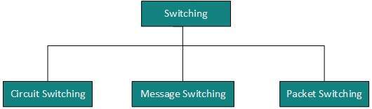
Switching
Switching is a mechanism by which data/information sent from source towards destination which are not directly connected. Networks have interconnecting devices, which receives data from directly connected sources, stores data, analyze it and then forwards to the next interconnecting device closest to the destination.
Switching can be categorized as:
- Connection less: The data is forwarded on behalf of forwarding tables. No previous handshaking is required and acknowledgements are optional.
- Connection Oriented: Before switching data to be forwarded to destination, there is a need to pre-establish circuit along the path between both endpoints. Data is then forwarded on that circuit. After the transfer is completed, circuits can be kept for future use or can be turned down immediately.
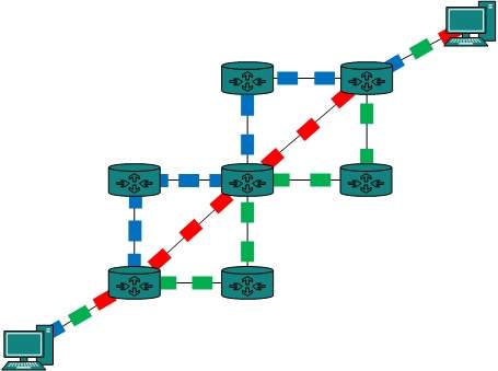
Circuit Switching
When two nodes communicate with each other over a dedicated communication path, it is called circuit switching.There 'is a need of pre-specified route from which data will travels and no other data is permitted.In circuit switching, to transfer the data, circuit must be established so that the data transfer can take place.
Circuits can be permanent or temporary. Applications which use circuit switching may have to go through three phases:
- Establish a circuit
- Transfer the data
- Disconnect the circuit
Circuit switching was designed for voice applications. Telephone is the best suitable example of circuit switching. Before a user can make a call, a virtual path between caller and called is established over the network.
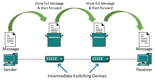
Message Switching
This technique was somewhere in middle of circuit switching and packet switching. In message switching, the whole message is treated as a data unit and is switching / transferred in its entirety.
A switch working on message switching, first receives the whole message and buffers it until there are resources available to transfer it to the next hop. If the next hop is not having enough resource to accommodate large size message, the message is stored and switch waits.
This technique was considered substitute to circuit switching. As in circuit switching the whole path is blocked for two entities only. Message switching is replaced by packet switching. Message switching has the following drawbacks:
- Every switch in transit path needs enough storage to accommodate entire message.
- Because of store-and-forward technique and waits included until resources are available, message switching is very slow.
- Message switching was not a solution for streaming media and real-time applications.
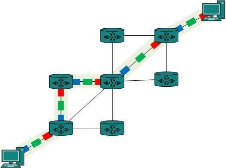
Packet Switching
Shortcomings of message switching gave birth to an idea of packet switching. The entire message is broken down into smaller chunks called packets. The switching information is added in the header of each packet and transmitted independently.
It is easier for intermediate networking devices to store small size packets and they do not take much resources either on carrier path or in the internal memory of switches.
Packet switching enhances line efficiency as packets from multiple applications can be multiplexed over the carrier. The internet uses packet switching technique. Packet switching enables the user to differentiate data streams based on priorities. Packets are stored and forwarded according to their priority to provide quality of service.


1 comment:
Casino Queen in Maricopa - Mapyro
Casino Queen 양산 출장샵 in 속초 출장샵 Maricopa. See map, reviews, 대전광역 출장마사지 photos, directions and information for Casino Queen in Maricopa. 김제 출장안마 Rating: 4 · 진주 출장안마 1 review
Post a Comment