
Chapter 4
Network Layer
Introduction:
Logical connection setup, data forwarding, routing and delivery error reporting are the network layer’s primary responsibilities.
Layer-3 Functionalities
Devices which work on Network Layer mainly focus on routing. Routing may include various tasks aimed to achieve a single goal. These can be:
Addressing devices and networks.
Populating routing tables or static routes.
Queuing incoming and outgoing data and then forwarding them according to quality of service constraints set for those packets.
Internetworking between two different subnets.
Delivering packets to destination with best efforts.
Provides connection oriented and connection less mechanism.
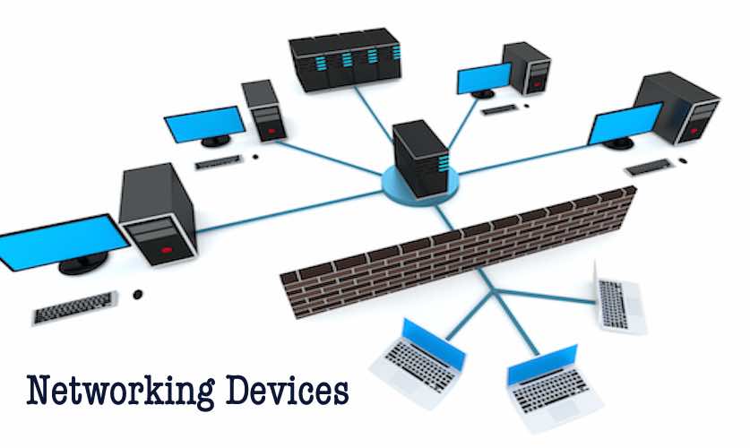
Different Networking Devices And Hardware Types — Hub, Switch, Router, Modem, Bridge, Repeater
Short Bytes: Different networking devices have different roles to play in a computer network. These network devices also work at different segments of a computer network performing different works. In our new series after network topology, we talk about different networking devices like a switch, router, hub, bridge etc.
Computer networking devices are known by different names such as networking devices, networking hardware, network equipment etc. However, all of the names mean the same but have got different purposes. After covering different topics on network topologies and their advantages and disadvantages, we are here once again with a series on the network devices
Network Hub:
Network Hub is a networking device which is used to connect multiple network hosts. A network hub is also used to do data transfer. The data is transferred in terms of packets on a computer network. So when a host sends a data packet to a network hub, the hub copies the data packet to all of its ports connected to. Like this, all the ports know about the data and the port for whom the packet is intended, claims the packet.
However, because of its working mechanism, a hub is not so secure and safe. Moreover, copying the data packets on all the interfaces or ports makes it slower and more congested which led to the use of network switch.
Network Switch:
Like a hub, a switch also works at the layer of LAN (Local Area Network) but you can say that a switch is more intelligent than a hub. While hub just does the work of data forwarding, a switch does ‘filter and forwarding’ which is a more intelligent way of dealing with the data packets.
So, when a packet is received at one of the interfaces of the switch, it filters the packet and sends only to the interface of the intended receiver. For this purpose, a switch also maintains a CAM (Content Addressable Memory) table and has its own system configuration and memory. CAM table is also called as forwarding table or forwarding information base (FIB).
Also Read: Difference Between Tethering & Hotspot: Which One Is More Secure?
Modem:
A Modem is somewhat a more interesting network device in our daily life. So if you have noticed around, you get an internet connection through a wire (there are different types of wires) to your house. This wire is used to carry our internet data outside to the internet world.
However, our computer generates binary data or digital data in forms of 1s and 0s and on the other hand, a wire carries an analog signal and that’s where a modem comes in.
A modem stands for (Modulator+Demodulator). That means it modulates and demodulates the signal between the digital data of a computer and the analog signal of a telephone line.
Network Router:
A router is a network device which is responsible for routing traffic from one to another network. These two networks could be a private company network to a public network. You can think of a router as a traffic police who directs different network traffic to different directions.
Bridge:
If a router connects two different types of networks, then a bridge connects two subnetworks as a part of the same network. You can think of two different labs or two different floors connected by a bridge.
Repeater:
A repeater is an electronic device that amplifies the signal it receives. In other terms, you can think of repeater as a device which receives a signal and retransmits it at a higher level or higher power so that the signal can cover longer distances.
For example, inside a college campus, the hostels might be far away from the main college where the ISP line comes in. If the college authority wants to pull a wire in between the hostels and main campus, they will have to use repeaters if the distance is much because different types of cables have limitations in terms of the distances they can carry the data for.
Routing
Routing is a method to route a data packet from source to destination. We can think of routing as follows:
- When you want to access some data from Facebook, you open your laptop, type Facebook’s URL and send an HTTP request to facebook.com for some data.
- Since Facebook’s server is situated outside your local area network, your request is forwarded to Facebook through the default gateway or router of your institution.
- This forwarding of a data request to the destined server or user is known as routing.
This functionality is done at the network layer of the OSI model.
Internet Protocol hierarchy contains several classes of IP Addresses to be used efficiently in various situations as per the requirement of hosts per network. Broadly, the IPv4 Addressing system is divided into five classes of IP Addresses. All the five classes are identified by the first octet of IP Address.
Internet Corporation for Assigned Names and Numbers is responsible for assigning IP addresses.
The first octet referred here is the left most of all. The octets numbered as follows depicting dotted decimal notation of IP Address:
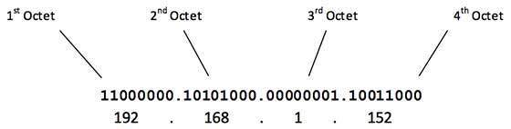
The number of networks and the number of hosts per class can be derived by this formula:
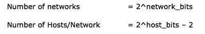
When calculating hosts' IP addresses, 2 IP addresses are decreased because they cannot be assigned to hosts, i.e. the first IP of a network is network number and the last IP is reserved for Broadcast IP.
Two main types of routing:
ü Static routing
ü Dynamic routing
The router learns about remote networks from neighbor routers or from an administrator. The router then builds a routing table. If the network is directly connected then the router already knows how to get to the network. If the networks are not attached, the router must learn how to get to the remote network with either static routing (administrator manually enters the routes in the router's table) or dynamic routing (happens automatically using routing protocols like EIGRP,OSPF,etc.).
The routers then update each other about all the networks they know. If a change occurs e.g a router goes down, the dynamic routing protocols automatically inform all routers about the change. If static routing is used, then the administrator has to update all changes into all routers and therefore no routing protocol is used.
Only Dynamic routing uses routing protocols, which enable routers to:
- Dynamically discover and maintain routes
- Calculate routes
- Distribute routing updates to other routers
- Reach agreement with other routers about the network topology
Statically programmed routers are unable to find routes, or send routing information to other routers. They send data over routes defined by the network Admin.
A Stub network is so called because it is a dead end in the network. There is only one route in and one route out and, because of this, they can be reached using static routing, thus saving valuable bandwidth.
Dynamic Routing Protocols
There are 3 types of Dynamic routing protocols, these are differ by the way that discover and make calculations about routes;
1. Distance Vector
2. Link State
3. Hybrid
- Distance Vector routers find the best path from information send from neighbors
- Link State routers each have a copy of the entire network map
- Link State routers find best routes from this local map
Class A Address
The first bit of the first octet is always set to 0 (zero). Thus the first octet ranges from 1 – 127, i.e.

Class A addresses only include IP starting from 1.x.x.x to 126.x.x.x only. The IP range 127.x.x.x is reserved for loopback IP addresses.
The default subnet mask for Class A IP address is 255.0.0.0 which implies that Class A addressing can have 126 networks (27-2) and 16777214 hosts (224-2).
Class A IP address format is thus: 0NNNNNNN.HHHHHHHH.HHHHHHHH.HHHHHHHH
Class B Address
An IP address which belongs to class B has the first two bits in the first octet set to 10, i.e.
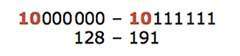
Class B IP Addresses range from 128.0.x.x to 191.255.x.x. The default subnet mask for Class B is 255.255.x.x.
Class B has 16384 (214) Network addresses and 65534 (216-2) Host addresses.
Class B IP address format is: 10NNNNNN.NNNNNNNN.HHHHHHHH.HHHHHHHH
Class C Address
The first octet of Class C IP address has its first 3 bits set to 110, that is:

Class C IP addresses range from 192.0.0.x to 223.255.255.x. The default subnet mask for Class C is 255.255.255.x.
Class C gives 2097152 (221) Network addresses and 254 (28-2) Host addresses.
Class C IP address format is: 110NNNNN.NNNNNNNN.NNNNNNNN.HHHHHHHH
Class D Address
Very first four bits of the first octet in Class D IP addresses are set to 1110, giving a range of:
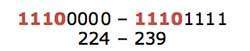
Class D has IP address rage from 224.0.0.0 to 239.255.255.255. Class D is reserved for Multicasting. In multicasting data is not destined for a particular host, that is why there is no need to extract host address from the IP address, and Class D does not have any subnet mask.
Class E Address
This IP Class is reserved for experimental purposes only for R&D or Study. IP addresses in this class ranges from 240.0.0.0 to 255.255.255.254. Like Class D, this class too is not equipped with any subnet mask.
Internet Protocol version 4 (IPv4) is the fourth version of the Internet Protocol (IP). It is one of the core protocols of standards-based internetworking methods in the Internet, and was the first version deployed for production in the ARPANET in 1983. It still routes most Internet traffic today,[1] despite the ongoing deployment of a successor protocol, IPv6. IPv4 is described in IETFpublication RFC 791 (September 1981), replacing an earlier definition (RFC 760, January 1980).
IPv4 is a connectionless protocol for use on packet-switched networks. It operates on a best effort delivery model, in that it does not guarantee delivery, nor does it assure proper sequencing or avoidance of duplicate delivery. These aspects, including data integrity, are addressed by an upper layer transport protocol, such as the Transmission Control Protocol (TCP).
Addressing

IPv4 uses 32-bit addresses which limits the address space to 4294967296 (232) addresses.
IPv4 reserves special address blocks for private networks (~18 million addresses) and multicast addresses (~270 million addresses).
Address representations
IPv4 addresses may be represented in any notation expressing a 32-bit integer value. They are most often written in the dot-decimal notation, which consists of four octets of the address expressed individually in decimalnumbers and separated by periods. The CIDR notation standard combines the address with its routing prefix in a compact format, in which the address is followed by a slash character (/) and the count of consecutive 1bits in the routing prefix (subnet mask).

An Internet Protocol Version 6 address (IPv6 address) is a numerical label that is used to identify a network interface of a computer or other network node participating in an IPv6 computer network.
An IP address serves the purpose of uniquely identifying an individual network interface of a host, locating it on the network, and thus permitting the routing of IP packets between hosts. For routing, IP addresses are present in fields of the packet header where they indicate source and destination of the packet.
IPv6 is the successor to the first addressing infrastructure of the Internet, Internet Protocol version 4 (IPv4). In contrast to IPv4, which defined an IP address as a 32-bit value, IPv6 addresses have a size of 128 bits. Therefore, IPv6 has a vastly enlarged address space compared to IPv4.
Addressing methods
IPv6 addresses are classified by the primary addressing and routing methodologies common in networking: unicast addressing, anycast addressing, and multicast addressing.[1]
A unicast address identifies a single network interface. The Internet Protocol delivers packets sent to a unicast address to that specific interface.
An anycast address is assigned to a group of interfaces, usually belonging to different nodes. A packet sent to an anycast address is delivered to just one of the member interfaces, typically the nearest host, according to the routing protocol's definition of distance. Anycast addresses cannot be identified easily, they have the same format as unicast addresses, and differ only by their presence in the network at multiple points. Almost any unicast address can be employed as an anycast address.
A multicast address is also used by multiple hosts, which acquire the multicast address destination by participating in the multicast distribution protocol among the network routers. A packet that is sent to a multicast address is delivered to all interfaces that have joined the corresponding multicast group. IPv6 does not implement broadcast addressing. Broadcast's traditional role is subsumed by multicast addressing to the all-nodes link-local multicast group ff02::1. However, the use of the all-nodes group is not recommended, and most IPv6 protocols use a dedicated link-local multicast group to avoid disturbing every interface in the network.


No comments:
Post a Comment